Figure 1
Home
< Thermal Aging
Thermal
Aging
Core Loss Increase Due to Thermal Aging in Iron Powder Cores
The following discussion and examples illustrate the phenomenon of thermal aging and detail the variables and conditions that effect a change in core loss characteristics. All iron powder cores, regardless of the manufacturer, are susceptible to permanent increases in core loss when exposed to elevated temperatures for extended periods of time. It is important for the design engineer to understand the conditions under which thermal aging can occur and incorporate this knowledge into their standard design process.
Thermal aging is an irreversible increase in core loss as a result of prolonged exposure to elevated temperatures. The extent of these changes and realized effect on the wound core are a function of the following variables; time, ambient temperature and air flow, core volume and shape, operating frequency, peak ac flux density, material type and core manufacturer. Eddy current loss will be the dominant loss at higher frequencies while hysteresis loss will be the dominate loss at lower frequencies. The contribution of each form of loss to the total is also affected by the operating flux density. It is the eddy current portion of the core loss which is affected by high temperature thermal aging.
The first example will illustrate what happens in a design that is dominated by core loss and uses an undersized core. This design utilizes a core that can not safely dissipate the high level of core loss even with the benefit of forced air.
The first design example is for a buck inductor operating at 80 kHz. The parameters are as follows:
The maximum ambient temperature is 60°C with forced air cooling supplied by a variable speed fan that provides less air flow at lower power levels.
The core selected is part number T106-52 wound with 14 turns of AWG-14 resulting in 1.72 W of copper loss. The peak AC flux density is 670 G at 80 kHz produces a core loss of 4.9 W. The combined loss is 6.62 W which calculates to a temperature rise of approximately 83C°in free standing air. Since the maximum ambient temperature specified for this part is 60°C the inductor can easily reach 140°C without the benefit of forced air. It should be noted that the core loss tolerances for Micrometals cores are +/-15%. Under worst case core loss conditions, the 4.9 W nominal can be 5.64 W resulting in a total loss of 7.36 W for a temperature rise of 95C°in free standing air. These temperatures are much too hot for a core operating under these conditions where eddy current losses are a significant portion of the total loss. The T106 size core can safely dissipate a total of 2.59 W for a 40C°temperature rise.
Caution, a warning flag should go up on a design that is core loss dominated and depends on the use of air flow to reduce the temperature particularly if it uses a variable speed fan. While the copper loss will decrease at lower power levels, this is generally not the case with core loss. Variable speed fans should not be used with core loss dominated designs. It is much easier to remove heat from a copper loss dominated design than a core loss dominated design. The copper winding radiates the heat while the core material has a thermal impedance barrier that must first be overcome. Additionally, the inductor can be several degrees hotter on the inside of the core and in the "shadow of the air flow".

Figure 1
The upper curve in Figure 1 illustrates how quickly the projected core loss increases due to the excessive operating temperature. It should be obvious the surface area of this design is much too small to safely dissipate the excessive core loss in spite air flow. Pages 64 and 65 show the "Total Power Dissipation (W) Vs Temperature Rise" for various sized Micrometals cores. These tables are useful to quickly determine if the design is capable of meeting a 40C°or less temperature rise.
The middle curve in Figure 1 illustrates the smallest physical core size that meet the design requirements and has a temperature rise of less than 40C°. This core is part number T130-8/90 wound with 19 turns of AWG-10 for a copper loss of about 1.0 W. The peak AC flux density has been reduced to 465 G at 80 kHz decreasing the core loss to 2.5 W. The graph predicts this design will safely operate at 100°C total temperature well past 100,000 hours.
The lower curve of Figure 1 shows part number T106-52 used under similar conditions to the first design except now the dc output voltage is 5 V instead of 12.3 V. With 14 turns of AWG-12 wire, the peak AC flux density has decreased to 305 G and core loss to 1.0 W. The combined core and copper losses are 2.04 W for a temperature rise of 33C°. This design will safely operate at 100°C total temperature for more than 100,000 hours.
The next design examples will illustrate differences using a much larger core size, operating at two differing frequencies and peak AC flux densities.
The first design is operating at 60Hz, 10 kG on Micrometals part number T300-26D. The calculated core loss is about 7.35 W and assuming a copper loss of 7.35 W, the combined loss of 14.7 W results in a 33C° temperature rise. The lower curve in Figure 2 predicts that the core loss does not change even after 100,000 hours at 125°C. Almost all of the core loss at this frequency is hysteresis loss and is unaffected at this temperature.
The upper curve in Figure 2 shows how quickly the core loss increases in a design operating at 40 kHz with a peak AC flux density of 283 G. While the total core loss of 7.35 W is the same as the 60 Hz example, the eddy current losses are now dominant and increase with constant exposure to 125°C.
Assuming the copper loss is 7.35 W, the total loss of this design is 14.7 W resulting in a temperature rise of 33C°at time zero. After 20,000 hours the core loss has increased to 9.5 W and the temperature rise now reaches 37C°. After 100,000 hours at 125°C, the core loss has increased to 12.5 W, pushing the temperature rise to 42C°. This design example is not an extreme case but illustrates how the temperature rise of the inductor continues to increase as a function of time and temperature.

Figure 2
Another popular application for iron powder cores is power factor correction boost chokes. This can be a very demanding application where core loss calculation is more complex and often misunderstood. This can lead to poor designs that will have reliability problems. For a detailed discussion of proper core loss analysis for PFC boost chokes refer to page 58 of this catalog. Also, the latest version of Micrometals design software includes a PFC core loss application.
|
Part
Number AL
(nH/N2 ) Turns AWG# Bpk @ 100
kHz (G) Core Loss
(mW/cm3) Core
Volume (cm3) Core Loss
(mW) Copper
Loss (mW) Total Loss
(mW) Wound
Surface Area (cm2) Maximum
Size (in) Delta T
(C°) Approx.
Core Cost (per piece) Thermal
LIfe (Hours) |
Table 1
The third design example is a PFC boost choke operating at 100 kHz with the following requirements:
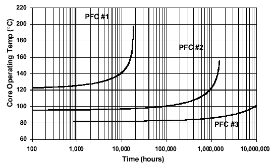
Referring to Table 1, you can see that design Solution #1 is a design that is dominated by 9.06 watts of core loss with only 0.87 watts of copper loss. This results in a temperature rise of 65C°. Figure 3 indicates that with an ambient of 55°C, this part will have thermal runaway in less than 2 years.
Solution #2 demonstrates that with the same core, by simply increasing the number of turns with the required smaller wire size, the core and copper losses will become more balanced. This results in improved efficiency (saving 4.3 watts), a lower operating temperature (T=41C°), and a dramatic improvement in thermal life (almost 2 orders of magnitude). While it may seem obvious that solution #1 is a poor design, this is a fairly common mistake.
If the higher inductance produced by adding turns in solution #2 is unacceptable in the circuit, the core and copper losses can also be better balance by selecting a lower permeability material. Solution #3 illustrates how the Micrometals 10µo (-2 Material) performs. This choke will be the most efficient and reliable, but this material type is more expensive than the -52 Material option.

Figure 3
Another important thermal aging consideration is the source of the iron powder cores, in other words, beware of "equivalent" iron powder cores. As demonstrated above, different materials will thermally age at different rates. This is also true with different manufacturers of core material. In many cases, the term "equivalent core" is solely based on dimensional and permeability characteristics.
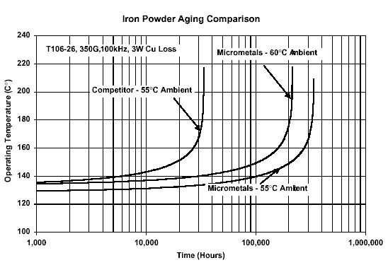
Figure 4 illustrates the thermal aging characteristic of Micrometals T106-26 at 100kHz with 350 G as well as the same winding on an "equivalent" competitor. The Micrometals core will safely operate for 300,000 hours whereas the competitor will runaway in less than 30,000 hours. Clearly, both cores are thermally aging at different rates.

Figure 4
Less obvious is the variation of initial core operating temperatures between the Micrometals and competitor cores. The competitors increased initial core temperature is a result of higher core losses. In another example, the ambient temperature for the Micrometals winding was increased to 60 °C to match the initial core operating temperature of the competitor. Again, the predicted difference in thermal life is dramatic.
As the example above demonstrate, evaluating one manufacturers core and substituting another at a later time can be a critical error. It is also very important to regulate the supply chain and monitor that sub-suppliers are not making any unknown core substitutions.