|
The following article is a synopsis of an application note written by Bruce Carsten for Micrometals, Inc. followed by a section on PFC Design Guidelines written by Micrometals. The unabridged original version of the Bruce Carsten application note is available upon request.
The boost preregulator “front end?is increasingly used with AC line inputs to obtain an (essentially) Unity Power Factor, or UPF. Calculations of the core losses in the main inductor is problematic, however, as AC flux in changing continuously in a complex manner even with “fixed?input and output voltages.
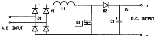
The basic AC-DC boost preregulator power circuit is shown in Figure 1. The operation of this circuit is generally well known; the duty cycle of the main switch Q1 is controlled by logic (not shown) to boost the rectified line input voltage “Vi?to the output voltage “Vo? while forcing the short term average input current (=L1 current) to be proportional to the instantaneous AC line voltage. Since the AC line voltage is (ideally) sinusoidal, the line current is also sinusoidal.
Figure 1
Basic Unity Power Factor boost preregulator
power circuit
The actual control technique and circuit used are largely irrelevant to the calculation of losses in UPF boost preregulators. The loss calculation approach used here is generally applicable to constant switching frequency circuits where the boost inductor current is above “critical? or continuous, throughout most of the AC line cycle.
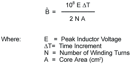
A sinusoidal input voltage, constant output voltage and constant conversion frequency are assumed for calculating the (relative) AC core and HF winding current losses in the main inductor (L1). The peak HF AC flux in the inductor core can be calculated from the switching voltage waveform. A convenient formula for peak AC flux ?ˆB ?in CGS units is:
The maximum flux ?ˆB max?occurs when:
Vi =Vo/2
Where:
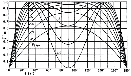
The actual switching frequency AC flux varies over the AC line voltage half cycle. Curves of ˆB / ˆB max vs. AC line phase angle q, for various ratios of Vi/Vo (where Vi = Peak AC Input Voltage) are plotted in figure 2
Figure 2
Relative Peak Flux in L1 Core vs. AC Input Voltage
and Phase
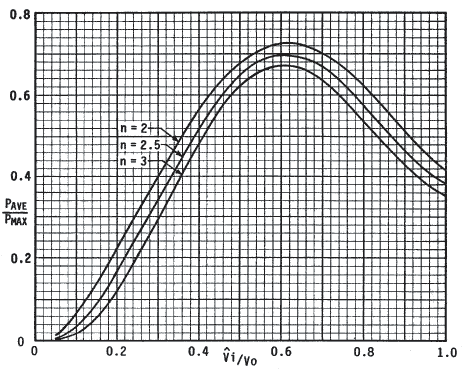
At a constant switching frequency, the core loss “Pfe? will vary as ˆB n, where the loss exponent “n?is typically between 1.65 and 3 for most magnetic materials, including powder iron materials. The ratio of average core loss (over an AC line voltage cycle) to the “maximum?loss (at Vi = Vo/2), for core loss exponents of 2.0, 2.5 and 3.0 are plotted in Figure 3.
Figure 3
Ratio of Average to Maximum Core Loss vs. Vi/Vo and Loss Exponent “n?/FONT>
It can be seen that the ratio of average/maximum core loss reaches a maxima when the peak AC line/DC output voltage ratio is near 0.61. The core loss ratio is not very sensitive to the core loss exponent, being somewhat less for higher loss exponents, with the largest average/maximum ratio only ranging from 0.672 for n = 3 to 0.725 for n = 2.
Since operation at the loss ratio maxima will occur in most UPF boost preregulators, a useful rule-of-thumb is that the “worst case?average core loss will be 70% of the loss calculated for Vi = Vo/2, where the Peak flux is:
Iron Powder PFC Design Guidelines
Extra care must be taken when designing and specifying iron powder cores for PFC applications due to the AC content and complexity of the core loss calculations. Most present day applications for iron powder cores can have ambient temperatures up to 55C? Therefore, the increase in temperature rise due to losses must be kept to a minimum.
It is important for a PFC design to be evaluated under the worst case conditions which will be at maximum power and in most designs when the peak input voltage is either at its lowest level or when the peak input voltage is .61 times the boost or output voltage. The worst case winding losses will occur at the lowest input voltage since this is when the maximum current will flow, but the worst case core losses will occur when the peak input voltage is .61 times the peak output voltage.
It is important to recognize that a PFC design dominated by core loss is not acceptable without first completing a thorough design analysis. It is generally recommended that the loss distribution be no greater than a 50/50% split between core and copper loss. In fact, a 20/80% or 25/75% split between core to copper loss is preferred. It is also important to remember that it is much easier to remove heat from the copper winding than from the core.
PFC applications mean that higher Peak AC Flux density conditions are often present in the core than traditional output choke applications. If an inappropriate core material or undersized core is selected, the core will be subjected to excessive high frequency core loss resulting in a temperature rise that can possibly lead to thermal failure.
Many designs today utilize variable speed fans in order to cool and “quiet down?the power supply. Even at a reduced power load condition, the effective AC flux density and resulting core loss of the PFC inductor can remain fairly constant. Only the copper loss (I2R) has been reduced. Extreme care should be taken since a reduction in fan speed can result in a higher than expected temperature owing to the reduction of air flow.
The best way to determine the “hot spot?core temperature is to drill a small hole midway into the core and install a thermocouple wire. The soundness of the thermocouple connection to the core is critical for accurate results. Close attention should be paid to the “shadow?areas that do not get the benefit of good air flow. These areas will be at a higher temperature than those directly in the air flow path. It is recommended that the unit is operated continuously under the worst case conditions for a period of 4 to 8 hours or until the inductor reaches thermal equilibrium. The true maximum temperature of the core can then be determined. Iron Powder core materials do have differing thermal conductivities which will effect their temperature gradient. Please refer to the Thermal Conductivity information.
Selecting a lower permeability core material will reduce the peak operating flux density and associated core loss. This reduction in core loss can be very significant and will, generally, more than offset any increase in winding losses.
The Micrometals Design Software is also available for a rapid solution to your requirements.
|

About Us
| What We Do
| Contact Us
| Samples
| Catalog
| Thermal Aging
| Parts
| Materials
| Software
| Home