 |
60 Hz Inductor Design
Requirements: 500 μH minimum from 1 to 5 amps of 60 Hz Current. |
| Consider minimum current level. |
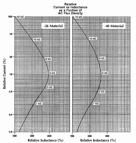
| For this example, the inductor must maintain 500mH minimum from 1 to 5 amperes, or down to 20% of full-rated current (I max). The importance of this consideration is illustrated by the graph above. This shows that, in the case of -40 Material, if the inductor is designed to operate at 10 kG at I max, that the inductance will be greater than or equal to L at I max down to 2.5 / 42 = 6.0% of I max. Likewise, if the inductor operates at 8 kG at I max, the inductor can only be operated down to 4.6 / 19.5 = 25% of I max before lower inductance will result. |
| Calculate Energy Storage Required (1/2 LI2 |
| 1/2 LI2 = (1/2) (500) (5) = 6250 μJ
|
| Select appropriate core size. |
| In this example -40 Material will be used. In order to maintain a minimum inductance down to 1 amp (20% of I max), the inductor must be designed to operate at greater than 8 kG at I max. This requires a core no larger than the E137 core or T131 toroidal core. To keep temperature rise down, the T131 will be selected. |
| Calculate the required Energy Storage (1/2 LI2) |
| 1/2 LI2 = (1/2) (45) (7.5)2 = 1266 μJ |
| Determine number of turns. |
| At 6250 μJ, the T131-40 indicates 235 ampere-turns.
NI = 235 N = 235 / 5 = 47 turns
|
| Select wire size. |
Since the ôsimple?winding results are a rough approximation of typical single-layer windings, the Single Layer Winding Table can be used as a guide in selecting the wire size. #19 will fit in a single layer and yield about 20C?temperature rise due to the winding losses.
Solution:
Part no. T131-40
47 turns #19 |